Wiring Guide for Mysa for Central HVACUpdated 2 months ago
This article is a wiring reference — not a hands-on install guide.
Here, you’ll learn about wire functions, system types, and the C-Wire requirement so you can plan your setup confidently.
When you’re ready to physically wire, mount, and power on your thermostat, continue to 👉 Mysa for Central HVAC Installation Guide.
Why Wiring Accuracy Matters
Each thermostat wire connects to a specific control in your HVAC system. Correct wiring ensures:
Continuous power to your Mysa for Central HVAC
Safe and stable system operation
Correct heating, cooling, and fan responses
Reliable smart features through the Mysa app
Incorrect or loose connections can prevent Mysa for Central HVAC from powering on or cause system errors. If anything looks unfamiliar, pause and contact an HVAC professional.
Understanding Terminals and Common Wires
Mysa for Central HVAC uses standard low-voltage (24 V) HVAC terminal labels. Use this table to identify your wires correctly. Wire colors are helpful, but always rely on terminal labels to identify wires.
Terminal | Function | Typical Wire Color | Notes |
R / RH / RC | 24 V power from transformer | Red | No jumper required for Mysa. The switch on the back of the main display is used to short Rc and Rh together for single transformer systems (default position) or separate for dual-transformer set-ups (open position). |
C | Common wire | Blue or Brown | Provides continuous power. Required for Mysa for Central HVAC. |
Y / Y1 / Y2 | Cooling compressor stages | Yellow | Y1 = first-stage cooling; Y2 = second-stage cooling. |
W / W1 / W2 | Heating stages | White | W1 = first-stage heat; W2 = second-stage |
| AUX/E | Auxiliary heat | Varies | 1 stage auxiliary heating |
G | Fan control | Green | For thermostat fan control. |
O/B | Reversing valve | Orange (O) / Dark Blue (B) | May be labeled O, B, or O/B. Used in heat pumps to switch between heating/cooling. |
S1 / S2 | Sensors | Varies | Optional wired temperature sensor connections. |
Tip: Trace wires to the control board to confirm connections.
Common confusions:
W vs AUX: For heat pump systems, W wires are usually auxiliary heat wires, especially if in a terminal with 2 different label sets - you may see W2, AUX, AUX/E.
W1 vs O/B: since these often share a terminal they can be confusing, however, a good indicator of which you have is whether or not you have a heat pump. For heat pumps this will be the O/B wire and is usually orange, whereas for conventional systems this will be the W wire.
O vs B: Both are reversing valve wires for heat pump setups. You should only have one or the other. Sometimes they are not differentiated, like on Mysa, and the label will be O/B. Some systems energize the valve in cooling (O wire), others in heating (B wire). Check your system documentation to see which yours controls. Alternatively, if you are unsure, Mysa defaults to the most common, O - energize reversing valve on cooling, when configuring your thermostat.
B vs C: B can be reused as a c-wire IF for heat pump systems there is also an O wire AND no other c-wire. Always confirm connections at the thermostat and on your furnace control board.
Wires Not in the List?
You may have other wires from your old thermostat that are not required for Mysa. These can be taped off and tucked inside the wall cavity. Some examples may include: T, L, M, VR
Reference Wiring Diagrams (for Planning & Verification)
Use these diagrams to verify or plan your wiring before installation.
Single-Transformer System (Heat / Cool Only)
Furnace / Boiler:
Furnace / Boiler T&T Terminals
Single or Two-Stage Heating or Cooling
Connections:
R, C, W1, W2, Y1, Y2, G
Existing C-Wire
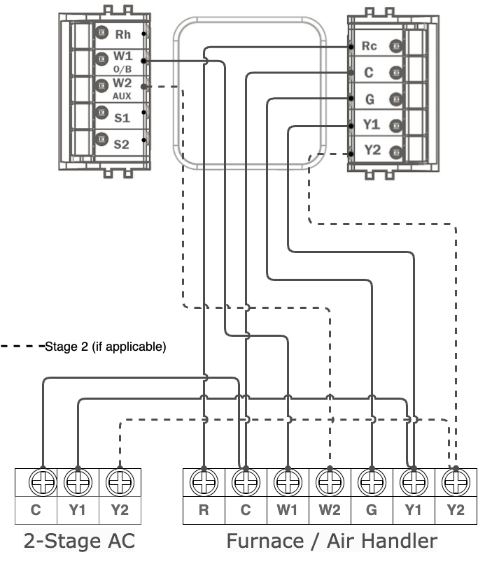 Image Caption
Mysa C-Wire Installation
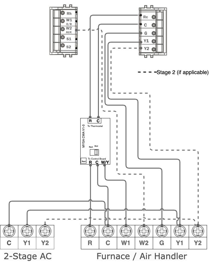
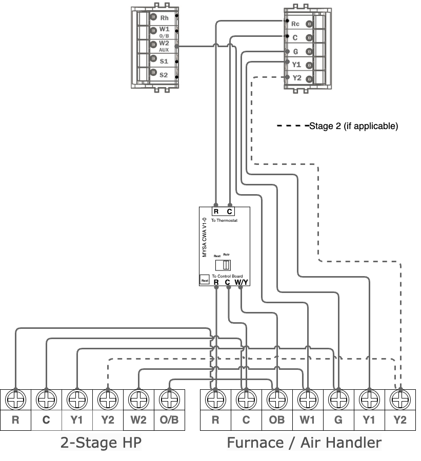
Single or Two-Stage Heat Pump System (O/B)
Connections:
R, C, Y, O/B, G, W/AUX
Existing C-Wire
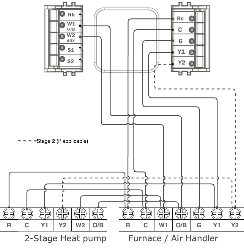
Mysa C-Wire Installation
Dual-Transformer Systems
If your system has separate transformers for heating and cooling:
⚠ Do not connect commons (C wires) between transformers.
Use an isolation relay or consult a professional.
Two Transformer Heat Pump + Boiler + Isolation Relay
![]()
Two Transformer AC + Boiler
![]()
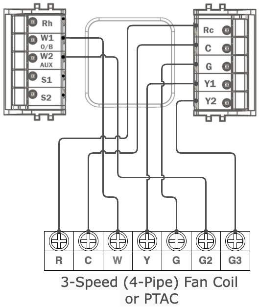
Fan Coil / PTAC Systems (Multi-Speed Fans)
The C-Wire: Power and Options
Mysa for Central HVAC requires a C-wire for continuous power. You have three options:
Use an existing C-wire — connect it to the C terminal on both ends.
Repurpose a spare wire — often brown or blue; connect to C at both thermostat and furnace or air handler control panel.
Install the Mysa C-Wire Power Adapter (CWA) — provides a reliable C-wire if none is available.
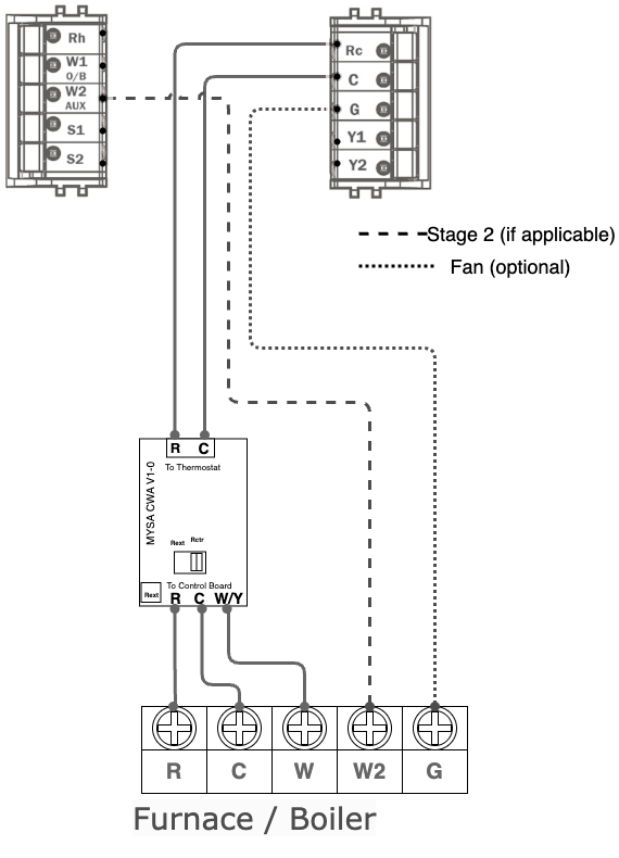
Installing the Mysa C-Wire Power Adapter (CWA)
The CWA installs near your furnace or air handler’s control board.
Key details:
Typically mounts next to the control board - adhesive pad or zip tie options available for mounting
15 in wire leads with labels and standard colors for ease of use
Clearly labeled R, C terminals going to thermostat and R, C, W/Y/OB terminals going to control panel
Converts your W/Y/OB wire to a C wire at the Mysa for Central HVAC thermostat
👉 See detailed C-Wire Adapter installation guide
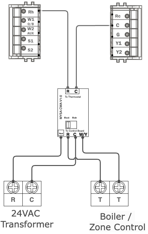
Multi-Zone Systems and Boilers
Zone valves: Each zone may use its own transformer — don’t tie commons together.
Boilers: “T/T” terminals are dry contacts. Use a CWA or external 24 V transformer for Mysa for Central HVAC power.

Troubleshooting Tips
If Mysa for Central HVAC doesn’t power up:
Check breaker and furnace door switch
Verify C-wire is connected both ends
Inspect 3–5 A fuse on furnace board
Confirm 24 V AC between R and C with a voltmeter
Related Articles & Next Steps
Configuring Mysa for Central HVAC